Software derived test equipment: Oscilloscope, Signal generator and more.
By: Steve Adams G0KVZ
This was originally presented to the Vange Amateur Radio Society on the 18th November 2010.
After basic hand tools, a soldering iron, and a multimeter,
two of the most commonly needed (and versatile) pieces of
equipment that one will need are an oscilloscope,
and a signal generator.
There is no substitute for these complex devices, and they are quite expensive.
But with today’s computers becoming increasingly fast, it is now possible to
install software that enables a standard P.C. to emulate their basic
functions.
It must be noted that these do not boast great specifications, but
despite the limitations of reduced functionality / bandwidth, these programmes
offer the user low-cost (free) alternatives that can perform very well for
audio troubleshooting.
Four such programmes are featured below, and will provide the
home constructor or radio amateur with basic equipment:
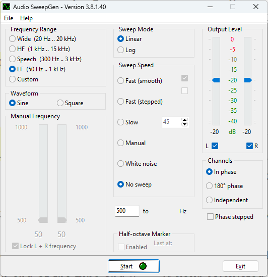
Signal generator:
This software was written by: David J Taylor.
and is available for download HERE
Description:
SweepGen turns a PC into an Audio Oscillator and Sweep Generator which can be used for testing audio or educational purposes. In conjunction with audio test instruments, you can make frequency response plots. SweepGen uses the sound card in your PC to produce sine waves that are mathematically correct almost to CD quality, indeed it's more likely that the quality of your PC sound card will be the limiting factor rather than the code in SweepGen.
A cable to utilise the output signal from the PC to be applied to the DUT.
This is just a length of coax with croc clips or a probe on one end, and a 3.5mm stereo jack plug on the other, Preferably a small coupling capacitor (0.1uF) should also be used.
Oscilloscope:
This software was written by: Christian Zeitnitz
and is available for download HERE Details:
The PC based Soundcard Oscilloscope receives its data from the Soundcard with 44.1kHz and 16 Bit resolution. The data source can be selected in the Windows mixer (Microphone, Line-In or Wave). The frequency range depends on the sound card, but 20-20000Hz should be possible with all modern cards. The low frequency end is limited by the AC coupling of the line-in signal. Be aware, that most microphone inputs are only mono.
The oscilloscope contains in addition a signal generator for 2 channels for Sine, Square, Triangular and Sawtooth wave forms in the frequency range from 0 to 20kHz. These signals are available at the speaker output of the sound card. These can be fed back to the oscillocope in order to generate Lissajous figures in the x-y mode.
Trigger modes: off, automatic, normal and single shot.
Triggerlevel can be set with the mouse.
The signals of the two channels can be added, subtracted and multiplied.
x-y mode.
Frequency analysis (Fourier spectrum).
Frequency filter: low-, high- and band-pass.
Cursors to measure amplitude, time and frequency in the main window.
Audio Recorder to save data to a wave file.
For multi soundcard system, the used card can be selected in the settings tab.
To enable a standard oscilloscope probe to be used
a 50 ohm bnc connector should be connected via screened cable to the tip and ring of a 3.5mm stereo jack plug.
Frequency-counter / instrument-tuner:
This software was written by: W.A. Steer PhD.
and is available for download HERE
Description:
The tuner samples the currently selected audio-in (set by your 'Recording' volume control panel) in one-tenth second chuncks. It then counts the number of complete wavecycles and divides by the time taken to obtain the frequency. The frequency is displayed in the top left, and is expressed as the nearest musical note plus or minus so-many cents (according to an equally tempered scale based on A as 440.0Hz).
The display is bright when the program believes it has a self-consistent reading. If the volume is too low (or fluctuating too much), the signal is rich in harmonics, or contaminated by extraneous sounds or electrical interference, then the display remains dim. If the signal is too loud then the display goes red.
Real-time Spectrum Analyser:
This software was written by: W.A. Steer PhD.
and is available for download HERE
Description:
This program uses the output from the 'Recording' mixer panel as its input.
Audio is sampled at 44.1kHz, with 16-bit resolution, mono. The FFT analyses 4096 samples at a time, yielding a transform with a resolution of 10.77Hz.
Version 2.2 features a peak level meter, and allows various vertical and horizontal scales to be chosen. For best results at least a Pentium II class processor is recommended.
[The now-obsolete version 2.2 from Jan 2003 is still available at specan22.exe just in case the new version has any new issues.]
The new version 2.8 now has a menu option to open the relevant volume mixer (especially useful in Windows XP). It is also now aware of -and can make use of- multiple soundcards (in XP) -- this same addition is a huge bonus under the new sound model of Vista/Windows7 where all the input devices appear like individual soundcards at the programming level.
At the presentation, these applications were demonstrated running on
modest equipment to illustrate the fact that one doesn't need a top-of-the range
computer to run this software on.
For the purpose of the demonstration I used an old Dell Inspiron 1100 (Celeron)
N.B. As the computer soundcard is not designed for use at high voltages
great care should be exercised to ensure that the computer is not damaged
as a result of using this software. this article (and the presentation)
should not be seen as recommending this software, and is not intended
as an endorsement.
Any loss or damage that is suffered as a result of using this software is entirely
at your own risk.
 Description:
 Details:
 Description:
 Description: